Separate sensors, separate setups.
Exploring ECG, muscle activity and optical sensing usually means managing different signal paths, interfaces and power requirements. This project brings those experiments into one portable prototype.
Founder’s featured project / educational prototype
ECG, EMG and optical sensing, integrated into one RP2040 system with a shared display and custom enclosure.
Read the story: starting problem → process & contribution → results → reflection. The technical guide and files follow.
Project in a minute
Exploring ECG, muscle activity and optical sensing usually means managing different signal paths, interfaces and power requirements. This project brings those experiments into one portable prototype.
The application displays an ECG waveform and pulse estimate, an adjustable EMG threshold, and MAX30102 red / infrared readings with a prototype oxygen-saturation estimate.
The project combines existing sensor modules and software references with application adaptation, physical integration and a Fusion 360 enclosure design.
The builder reports that the display, controls and all three modes operated successfully. Original code, two STL meshes and the build documentation are available. Accuracy against a medical reference instrument has not been established.
My contribution
Eason Yang’s project work spans integration, application adaptation, enclosure design and debugging. The project uses commercially available modules and existing software references.
I integrated the STEPico controller, ECG, EMG and optical modules, display and controls into a single prototype. The wiring record follows the application’s GPIO assignments and my recorded supply connections.
I adapted the MicroPython application around a shared TFT display, mode button, optical reset and adjustable EMG threshold. The application and dependency files are available for inspection.
I developed the Fusion 360 enclosure layout around the boards, display, openings and mounting space. Three CAD studies and two original enclosure meshes document this work.
I tested the display, controls and three modes. The development record also describes replacing a STEPico after an operating and heating problem.
STEPico, AD8232, MAX30102, the EMG amplifier, MEGO Dual and ST7789 are existing hardware modules. The application draws on EIM’s biomedical reference code and supplied libraries, fonts and the st7789 display driver. Original file attributions are retained. The contribution is the prototype’s integration and development; reference modules and library code are credited separately.
Results & evidence
Build photographs document the breadboard wiring, live display and physical enclosure assembly. Eason confirmed that the controls and all three modes operated.
Open the offline photo record →
| Check | Method / evidence | Result and limit |
|---|---|---|
| Display, controls & three modes | Prior use of the physical prototype, confirmed by the builder on 21 Oct 2026. | Eason’s operation check The test date, detailed procedure and measurement log are not recorded. |
| Runtime & display driver | Recorded Pico Shell output: sys.implementation and import st7789. | Recorded output MicroPython 1.20.0 on RP2040; display import succeeds. The original UF2 image is unavailable. |
| Optical calculator behaviour | Host checks for reset, flat input and complete synthetic waves; separate zero-baseline stress input. | Passes with a known edge case Reset and normal synthetic checks pass; the zero-baseline case raises ZeroDivisionError. This does not measure SpO₂ accuracy. |
One documented iteration / August 2025
The build record describes an operating fault and observed heating.
The STEPico controller was replaced.
The record reports restored operation and no further observed heating. It does not establish the fault’s cause.
This is an educational prototype. EMG conditioning, negative rail voltage and body-connected isolation remain unverified in this record. Read the power and assembly notes →
Reflection & next steps
The build demonstrates an integrated prototype: three sensing modes sharing a controller, display and enclosure. The controller replacement records a useful debugging result, while leaving the original fault’s cause unresolved.
The next step is a dated demonstration of the controls and screen responses, followed by separately documented checks of measurement accuracy. A future code revision can address the optical calculator’s zero-baseline error.
Recording the original firmware image, enclosure print settings and fastening details would make the build easier for another student to reproduce. The supplied code and design files remain available below.
Continue to the technical record ↓Build guide / technical documentation
Start with the module references, then follow the wiring, controller setup and source notes. The complete ZIP includes an offline entry page.
Hardware evidence
Physical module references
Product reference photos and details from the supplied screenshots. Each card includes source credit and the original build photograph.
USB-C connector, BOOT / RUN buttons and four on-board LEDs. Detail from the supplied CAD layout.
Front-view illustration of the ECG breakout. The supplied board photograph identifies 3.3V, GND and OUTPUT.
Product reference for the 1.54-inch, 240 × 240, eight-pin SPI display. Check terminal labels on the supplied board.
MH-ET LIVE breakout, shown from the labelled rear. VIN, SDA, SCL and GND are the four connections used in this build.
Reference illustration matching the module layout. The supplied board has +VS / GND / -VS and SIG / GND; its amplifier IC remains unconfirmed.
The supplied Fusion archive is named “mego dual” and complements the earlier visual match. The connection record routes MEGO +VCC to EMG +VS, and -VEE to -VS. The positive output is reported as +5 V; the negative voltage setting remains unverified.
| Part / module | Qty. | Role and evidence |
|---|---|---|
| STEPico / RP2040 | 1 | CAD label + program Main controller; ADC, SPI display, software I2C, buttons, and indicator. |
| ST7789 1.54-inch, 240 × 240 TFT | 1 | CAD label + program Shared display for the three operating modes. |
| AD8232 ECG breakout | 1 | Photograph + CAD label The photograph identifies the 3.3V, GND and OUTPUT terminals. The program assigns ECG sampling to GP28. |
| MAX30102 breakout | 1 | CAD label + driver import Red and infrared optical samples over software I2C. |
| EMG amplifier module | 1 | Supplied photograph; chip identity unconfirmed The board has +VS / GND / -VS power terminals and SIG / GND output terminals. A specific amplifier chip cannot be identified from the photograph. |
| MEGO Dual power module — Body1 reference | 1 | CAD archive supplied; wiring reported by builder The supplied Fusion archive is named mego dual. The connection record routes +VCC and -VEE to EMG +VS and -VS. The positive output is reported as +5 V; the negative voltage setting is not verified. |
| Potentiometer | 1 | CAD label + program Adjusts the EMG threshold through GP26. Resistance value is unconfirmed. |
| Pushbuttons | 2 | CAD labels + program Mode selection and oximeter sampling reset. |
| Printed enclosure parts | 2 | Uploaded STL files Two original meshes. Print settings, fasteners, and final fit still need a documented build record. |
Pictorial wiring guide
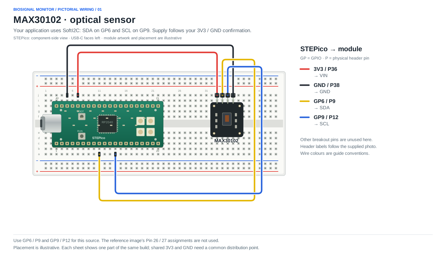
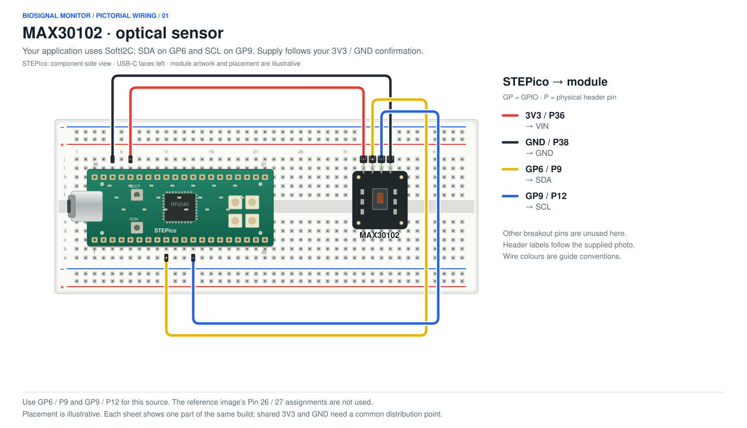
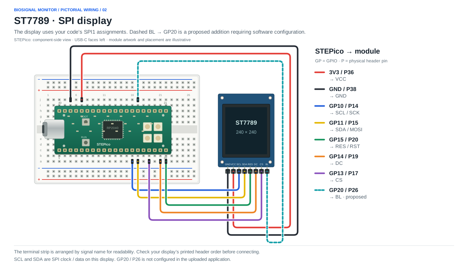
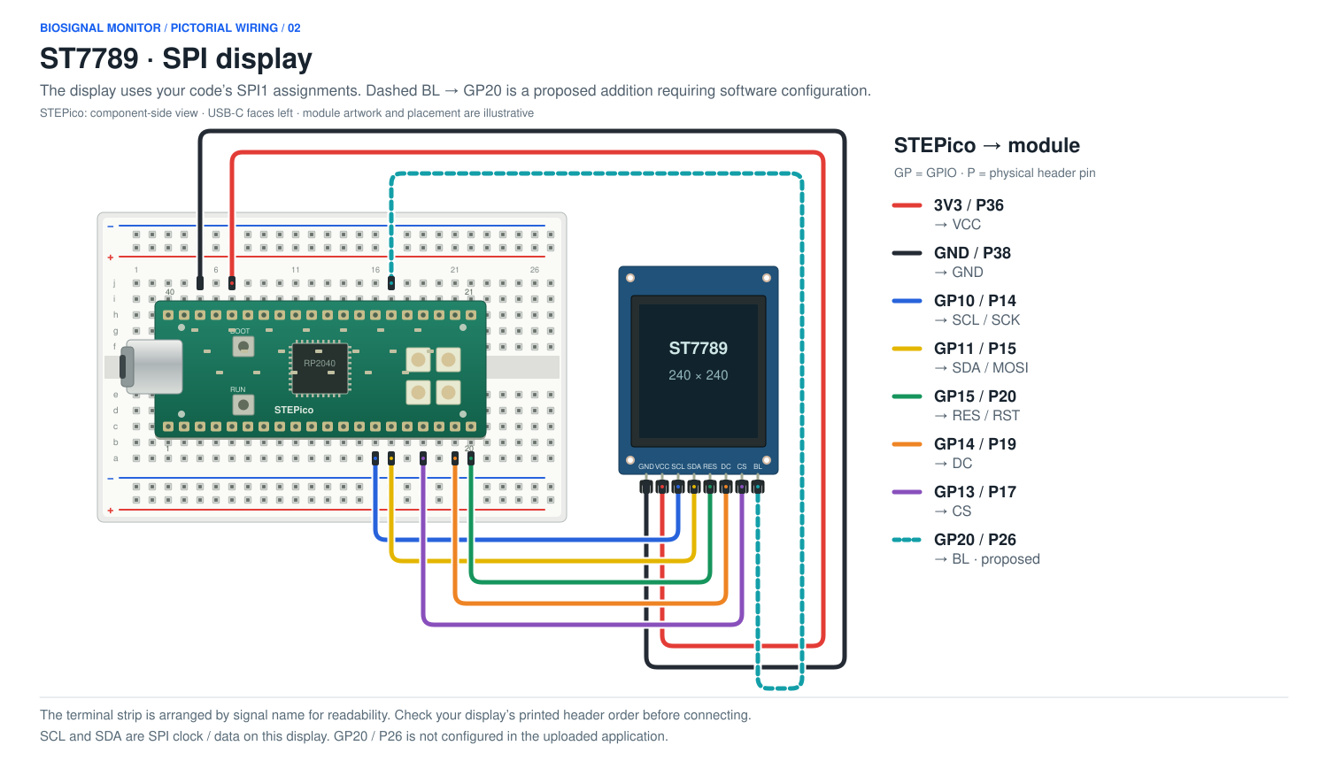
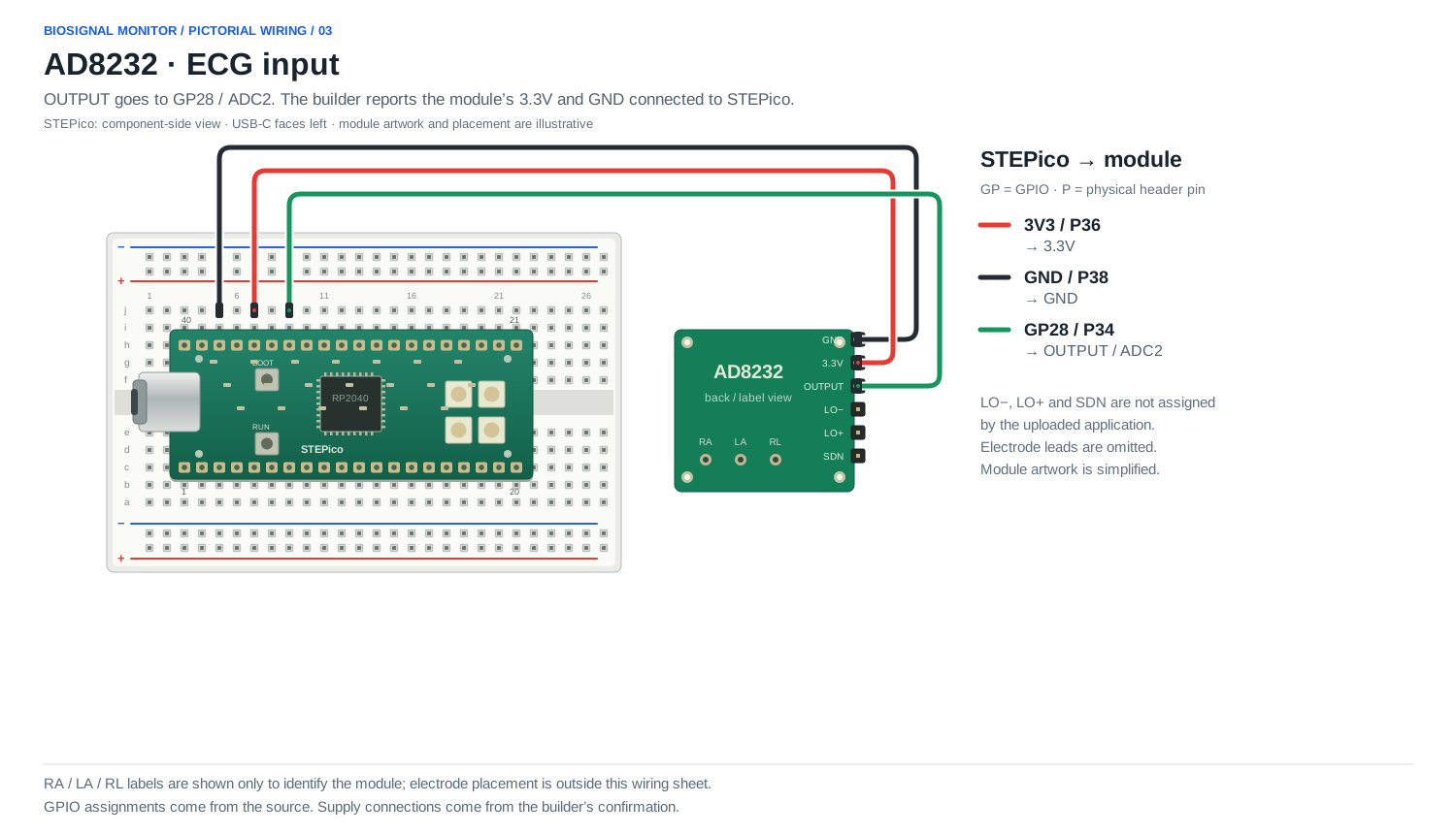
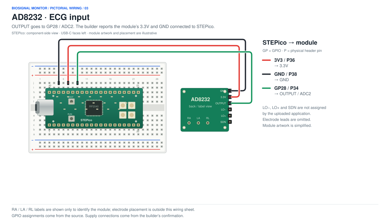
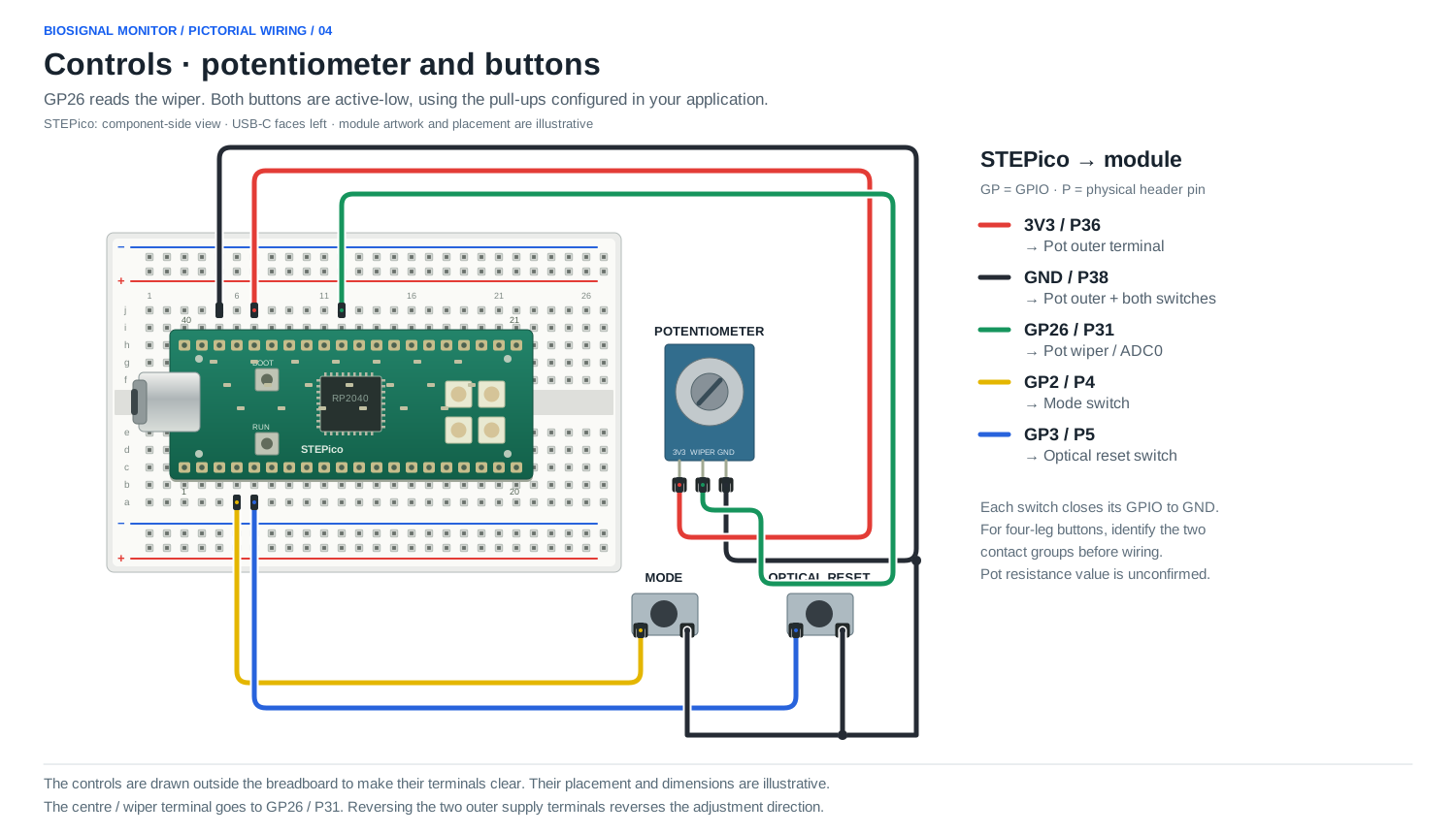
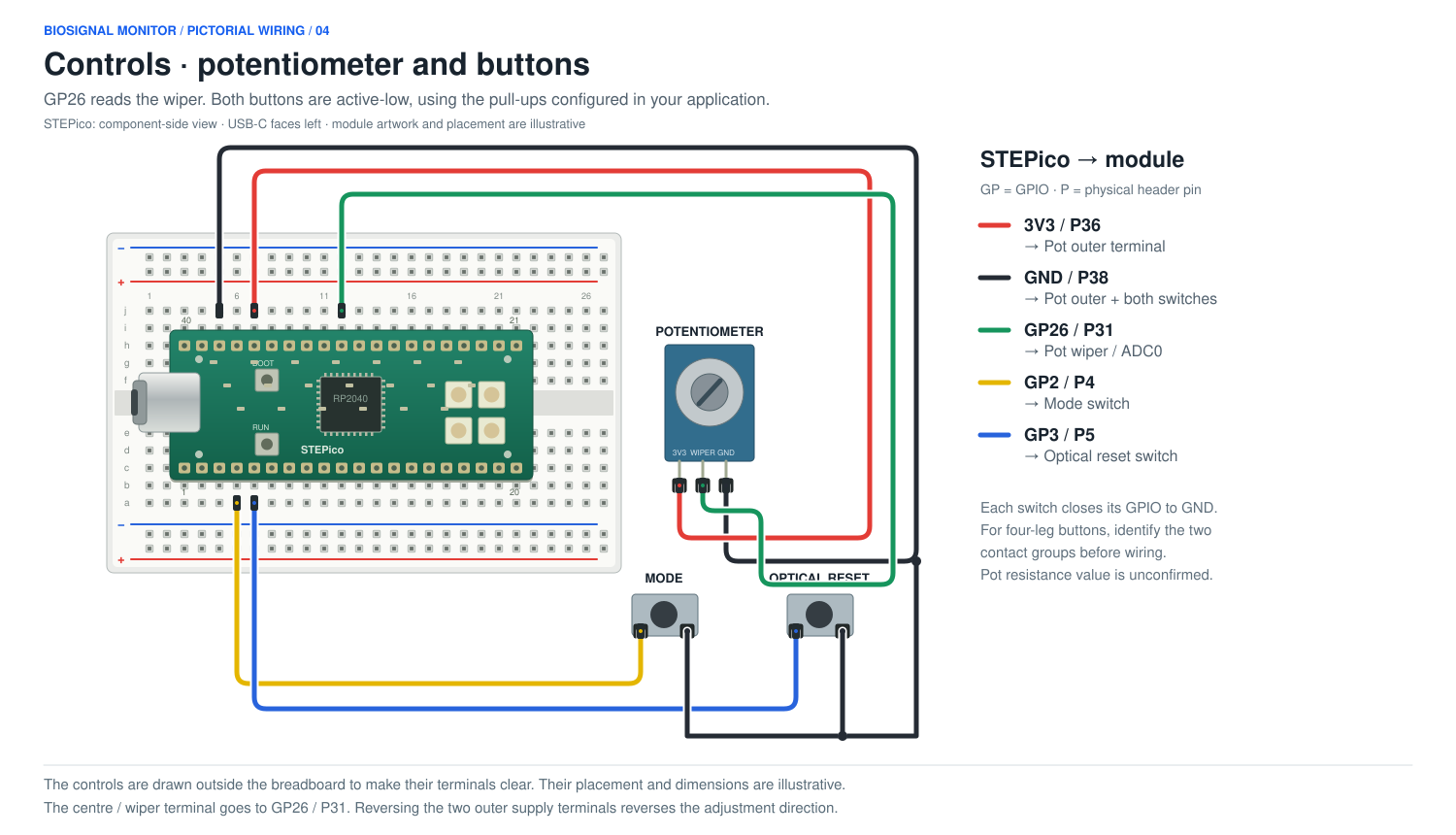
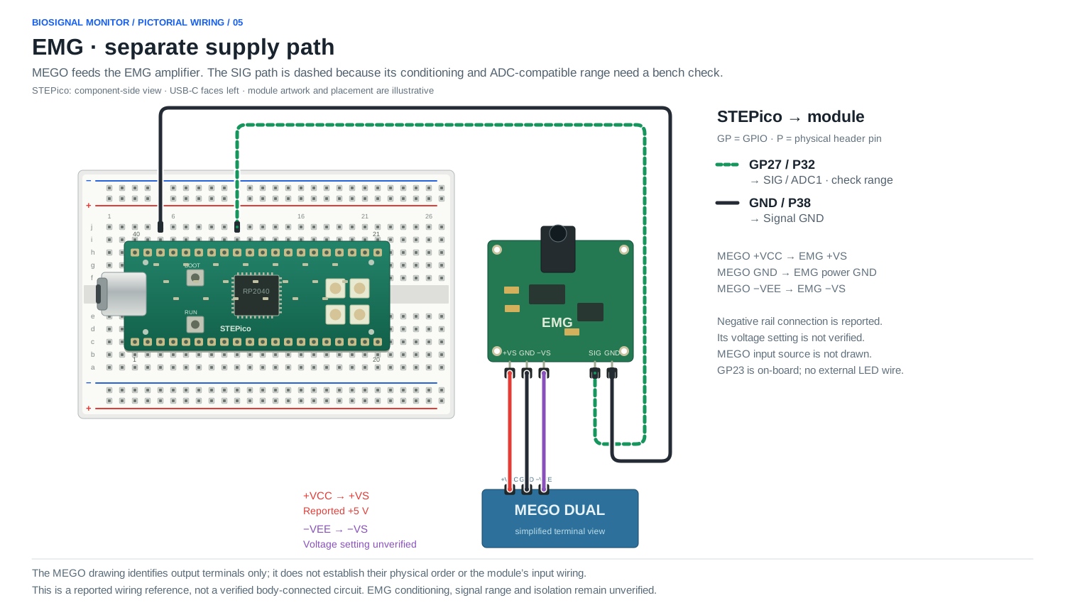
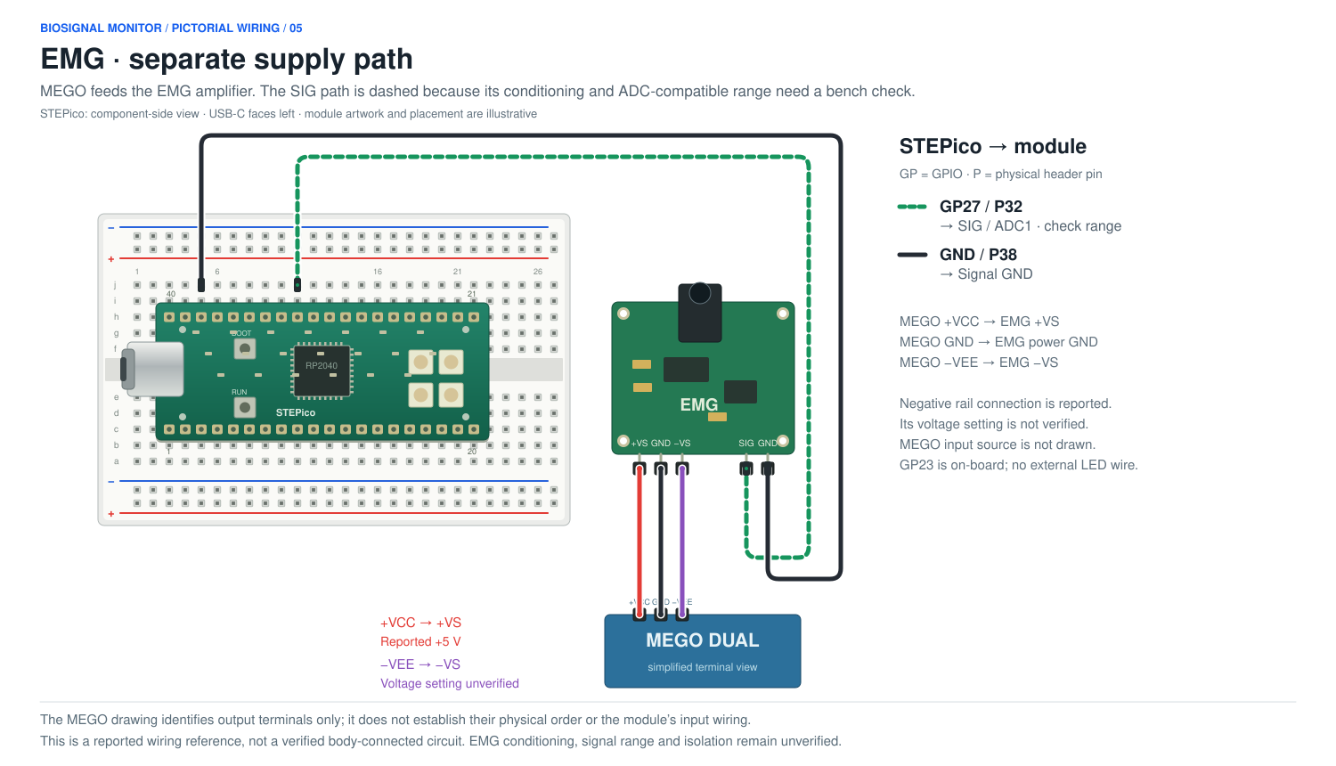
Five breadboard-style sheets pair coloured jumper paths with GPIO labels and physical header-pin numbers. Each sheet shows one part of the same system. Module artwork and placement are illustrative; source assignments, builder-reported supplies and proposed additions are labelled separately.
Use a shared distribution point for 3V3 and GND when combining the sheets. Match module terminal names to the board’s printed labels. The display sheet arranges its terminal strip for readability; its physical header order still needs confirmation.
Download all five wiring sheets ↓Source overview
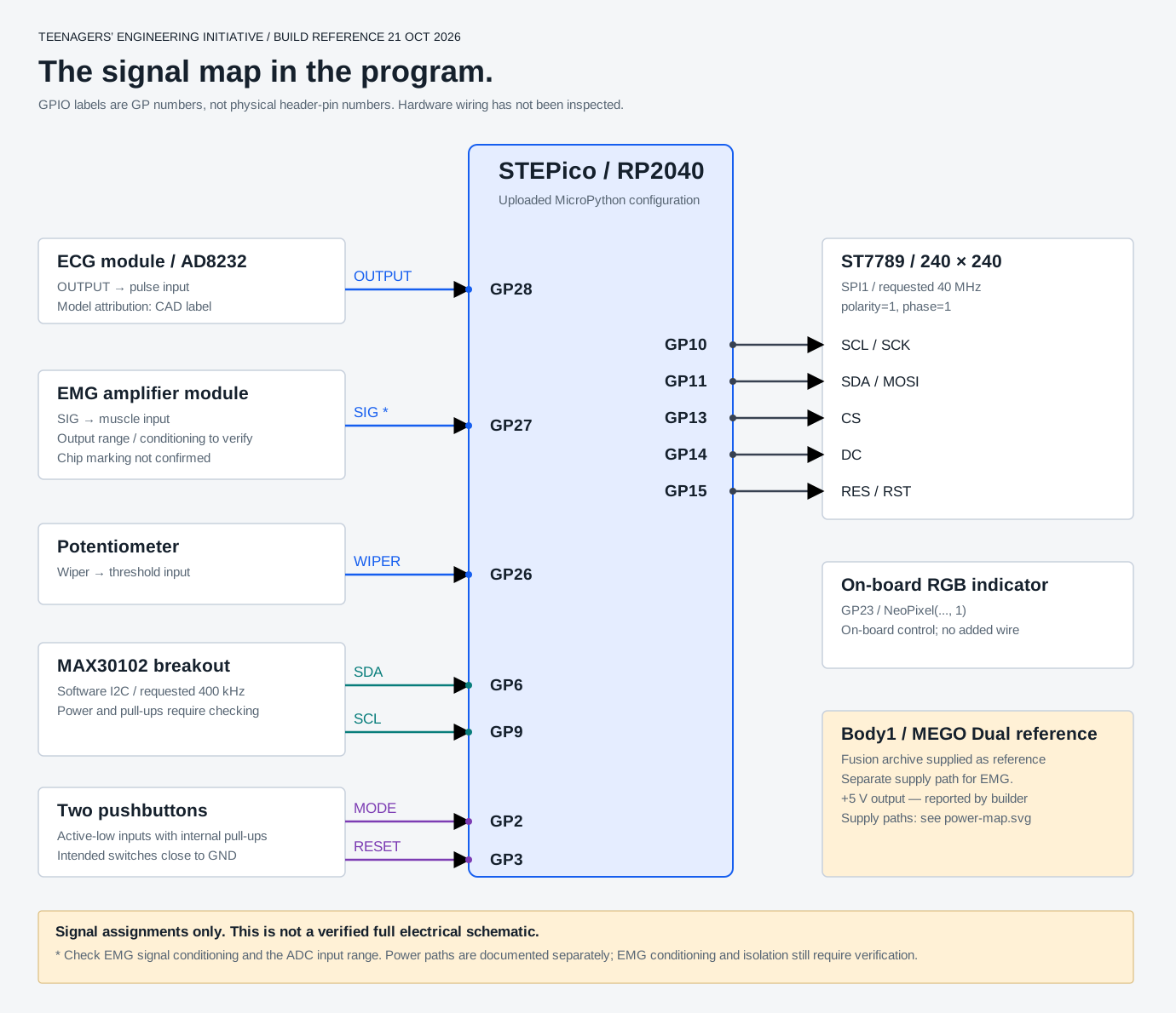
The original overview and source evidence are retained below. GP labels are GPIO numbers. The power diagram records supply connections; the proposed GP20 backlight path is absent from the uploaded program.
| Function | Signal / GPIO | Source and interpretation |
|---|---|---|
| ECG analog input | AD8232 OUTPUT (module attribution from CAD)GP28 / ADC2 | pulse = ADC(28)Source line 38The ADC assignment is explicit; the physical wire has not been inspected. |
| EMG analog input | EMG module SIGGP27 / ADC1 | muscle = ADC(27)Source line 53The supplied photograph establishes the module's +VS, GND, -VS and SIG labels. Its chip marking is not legible; check output conditioning and range before an ADC connection. |
| Threshold control | Potentiometer wiperGP26 / ADC0 | pot = ADC(26)Source line 54The potentiometer adjusts the software threshold. The builder reports 3V3 and GND supply connections for the modules other than EMG. |
| Display clock | ST7789 SCL / SCKGP10 | SPI(1, ... sck=Pin(10))Source line 31SPI clock. The display's SCL label is not an I2C connection in this program. |
| Display data | ST7789 SDA / MOSIGP11 | SPI(1, ... mosi=Pin(11))Source line 31SPI data into the display; no display MISO is specified. |
| Display chip select | ST7789 CSGP13 | cs=Pin(13, Pin.OUT)Source line 32SPI1 is requested at 40 MHz with polarity=1 and phase=1. |
| Display data / command | ST7789 DCGP14 | dc=Pin(14, Pin.OUT)Source line 32Control signal. |
| Display reset | ST7789 RES / RSTGP15 | reset=Pin(15, Pin.OUT)Source line 32The program does not assign a backlight pin. |
| Oximeter data | MAX30102 SDAGP6 | SoftI2C(sda=Pin(6), ...)Source line 72Software I2C, requested at 400 kHz. Keep this assignment when using this source. |
| Oximeter clock | MAX30102 SCLGP9 | SoftI2C(... scl=Pin(9), ...)Source line 72This is the uploaded SoftI2C configuration, rather than a generic hardware-I2C pin pair. |
| Mode button | Normally-open pushbuttonGP2 | Pin(2, Pin.IN, Pin.PULL_UP)Source line 17The code expects a high-to-low transition. Closing the switch to GND is the intended active-low arrangement. |
| Oximeter reset button | Normally-open pushbuttonGP3 | Pin(3, Pin.IN, Pin.PULL_UP)Source line 70A low input resets the red/IR calculation buffers; this does not establish medical calibration. |
| RGB indicator | STEPico on-board LED chainGP23 | rgb_pin = Pin(23)Source line 63–64The source addresses one NeoPixel. No external LED connection is inferred. |
Standard RP2040 ADC inputs use a 0–3.3 V range. Check the EMG output range and conditioning before connecting it to GP27. Amplifier supply voltage does not establish a compatible ADC signal range. The builder’s power connections are recorded below; the analog conditioning and isolation arrangement still need a bench check.
This is a bench-level educational reference. Body-connected use requires a separately checked, isolated measurement setup and qualified supervision.
Power & assembly
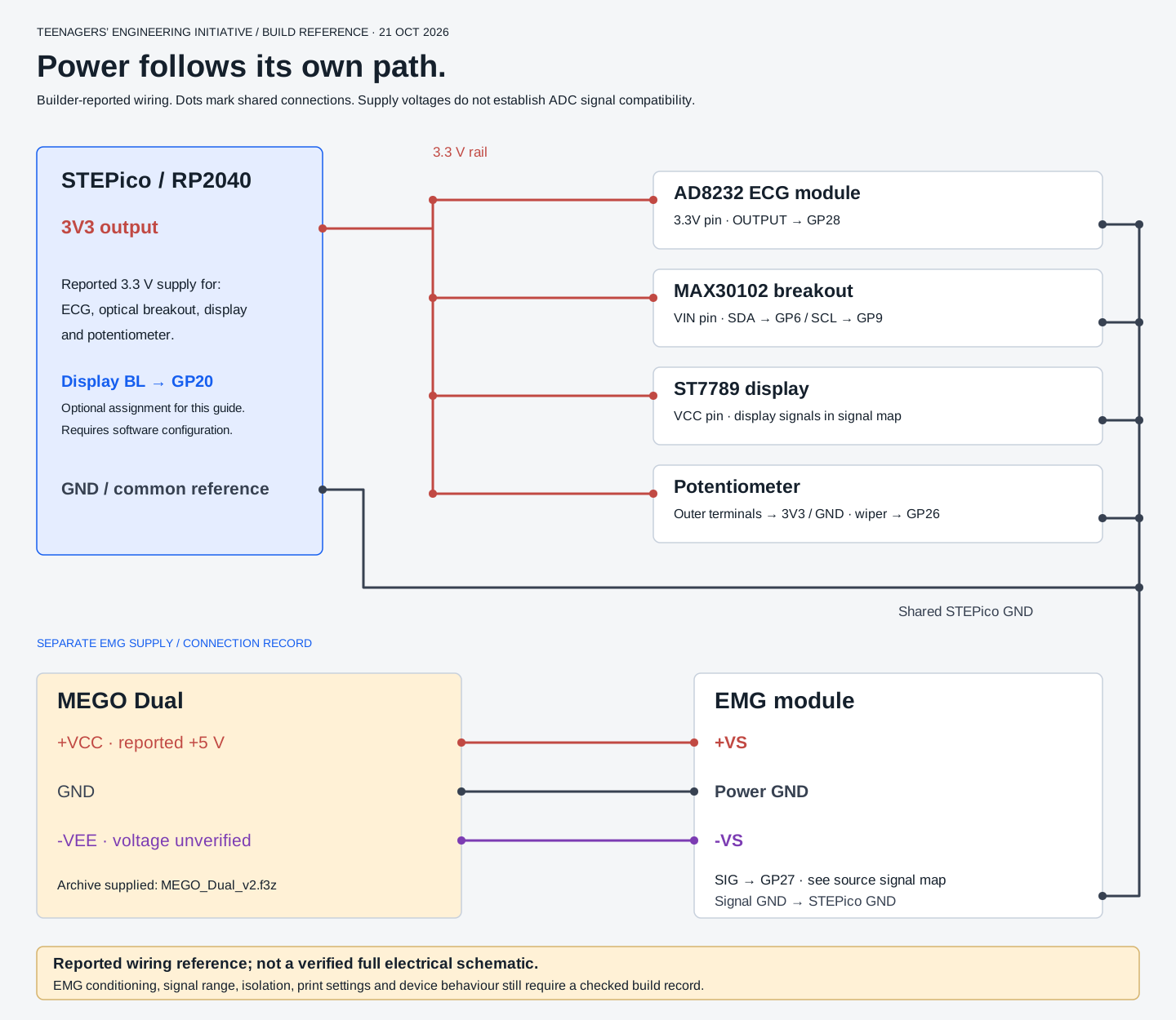
The builder confirms STEPico 3V3 and GND for the modules other than EMG. The EMG supply path follows the connection record. GP20 is an optional backlight assignment selected for this guide; it is not configured in the uploaded application.
| Module | Supply connection | Ground and evidence |
|---|---|---|
| AD8232 | 3.3V → STEPico 3V3 | GND → STEPico GND Builder confirmation + photographed pin labels |
| MAX30102 breakout | VIN → STEPico 3V3 | GND → STEPico GND Builder confirmation + photographed pin labels |
| ST7789 display | VCC → STEPico 3V3 | GND → STEPico GND Builder confirmation |
| Potentiometer | Outer terminals → STEPico 3V3 and GND; wiper → GP26 | Common STEPico GND Builder supply confirmation; GP26 from source |
| EMG module | +VS → MEGO +VCC; -VS → MEGO -VEE | Power GND → MEGO GND; signal GND → STEPico GND Builder connection record; positive output reported +5 V, negative voltage unverified |
| Display backlight — proposed | BL → GP20; requires matching software configuration | Common STEPico GND Optional assignment selected for this guide; not present in the uploaded program |
Assembly outline
Open both enclosure meshes and compare the board positions with the CAD layout. Use the MEGO archive as a component reference. Verify STL scale in the slicer.
Record the material, print orientation, settings, fasteners and clearances used for the actual build. These details are not established by the supplied meshes.
Use the photographs to identify connectors and pin labels. Plan access to USB-C, the display, controls and sensor connectors before securing the boards.
Follow the reported 3V3 and common GND connections. Keep the separate EMG supply path clearly labelled and check analog output conditioning and range.
Follow the source GPIO table. MAX30102 uses SoftI2C on GP6 / GP9. GP2 selects the mode; GP3 resets the optical calculation buffers.
The builder reports prior successful tests of the display, controls and all three operating modes. The current record includes MicroPython 1.20.0 and a successful st7789 import.
The supplied August 2025 build log reports that replacing the STEPico restored operation and stopped the observed heating. The cause of the earlier fault was not established.
STEPico installation
Follow these six steps for a new board. A board already running compatible MicroPython with st7789 can continue at step 5. The workflow adapts the manufacturer’s STEPico guide to this project’s display driver and Python files.
The builder’s Shell reports MicroPython 1.20.0 on RP2040 and successfully imports st7789. The builder confirms earlier hardware tests passed. The original firmware image is unavailable; the supplied files listed below do not identify that image.
Install Thonny from thonny.org. Connect STEPico with a USB-C data cable.
Use an RP2040 / Raspberry Pi Pico build that provides the st7789 display driver. The builder’s working board reports MicroPython 1.20.0; the exact original firmware image is unavailable. The driver project provides precompiled RP2 firmware as an upstream reference.
Hold BOOT, press and release RUN, then release BOOT. Alternatively, hold BOOT while plugging in USB. A drive named RPI-RP2 should appear.
Drag the compatible .uf2 file onto RPI-RP2. STEPico restarts and the drive disappears. This installs the runtime; Python files are transferred through Thonny afterwards.
In Thonny, select the MicroPython Raspberry Pi Pico / RP2040 interpreter and the board’s serial port. Open the Shell. For a new installation, import st7789 to confirm that the display driver is available.
Extract application-source.zip. In Thonny’s Files view, copy the four root Python files and the max30102 folder to the device root, preserving both files inside that folder. Open main.py and choose Run current script (F5).
Firmware installs the board’s runtime. main.py and its libraries are copied into that runtime’s filesystem. On a fresh board, the upstream st7789 project’s precompiled RP2 build is a driver-inclusive reference; it has not been confirmed as the builder’s original image.
Device root
| Path on Pico | Purpose |
|---|---|
main.py | Project application |
SpO2Calculators.py | Supplied calculator with reset() |
vga1_16x16.py | 16 × 16 display font |
vga1_8x8.py | Font imported at startup |
max30102/__init__.py | Optical sensor driver |
max30102/circular_buffer.py | Driver buffer dependency |
Internal version strings and UF2 block structure were inspected. These files are not the current board’s reported 1.20.0 image, and their display-driver compatibility has not been established. They are recorded as references and are not bundled as project firmware.
| Supplied filename | Internal version |
|---|---|
| RPI_PICO-20250415-v1.25.0.uf2 | 1.25.0 |
| RPI_PICO-20250809-v1.26.0.uf2 | 1.26.0 |
| RPI_PICO-20260824-v1.29.0.uf2 | 1.29.0 |
Software and behaviour
Reads GP28, draws a trace, and estimates BPM from threshold crossings in a ten-second window.
Reads GP27 and compares it with the potentiometer on GP26. The source’s displayed voltage scale needs review.
Reads MAX30102 over software I2C. GP3 resets the calculation buffers; GP23 drives the on-board indicator.
The source ZIP now contains main.py, the latest supplied SpO2Calculators.py, the MAX30102 package and both fonts. File contents are unchanged; names and directories match the program’s imports. The Pico reports MicroPython 1.20.0 on RP2040. The supplied Shell output confirms that st7789 imports successfully, and the builder reports prior hardware tests passed.
st7789The Pico reports MicroPython 1.20.0 on RP2040, and the supplied Shell output confirms import st7789 succeeds. The original firmware image was not supplied; no firmware is bundled.max30102Both __init__.py and circular_buffer.py are included unchanged in the max30102 directory. The newly supplied buffer matches the earlier copy.SpO2Calculators.pyThe latest device copy includes reset() and a guard for incomplete cycles. Constructor, reset and synthetic-wave checks pass on the host; zero-denominator handling still needs work.vga1_16x16.pyIncluded unchanged. The 16 × 16 font imported as myfont.vga1_8x8.pyIncluded unchanged. Imported at startup even though font8 is not used later in this source.The latest calculator includes reset() and an incomplete-cycle guard. Host checks pass for reset, flat input and complete synthetic waves. A zero-baseline stress check still raises ZeroDivisionError. The buffer’s pop_head() issue lies outside this application’s current pop-from-storage read path. The builder reports successful prior operation of the display, controls and all three modes. The host stress finding is retained as an edge case for a future code revision.
Extract the ZIP and preserve its directory structure. The five root entries are main.py, SpO2Calculators.py, vga1_16x16.py, vga1_8x8.py and the max30102 folder, which contains __init__.py and circular_buffer.py. Use Thonny’s Files view to copy them to the device root after preserving the existing device files.
The builder’s Pico returns <module 'st7789'> when importing the display driver. For a fresh Pico, the Python source ZIP requires a compatible runtime with this driver available. A .uf2 file is a board firmware image, installed separately from the Python application; the builder’s original image has not been supplied.
read_u16() by 30000. The standard full-scale mapping uses 65535, so its displayed “voltage” should be treated as a prototype scale until checked.The supplied source is preserved unchanged. Hardware test status is recorded from the builder’s confirmation.
Project downloads
Source release · 22 Oct 2026 · original application, supplied fonts and meshes, MEGO reference CAD, and documented signal and power connections.
Everything in one ZIP
Code, supplied libraries, both STL meshes, MEGO reference CAD, five wiring sheets, module and build photographs, and offline tutorials in one ZIP. Extract it and open START_HERE.html.
Six unchanged Python files: main.py, the latest supplied calculator, the MAX30102 package and both fonts, arranged for copying to the Pico. The display driver imports successfully; the builder reports prior hardware tests passed.
Both original meshes: ECG_Part_1.stl and ECG_Part_2.stl. Check model scale, orientation, clearances, and slicer settings before printing.
Five breadboard-style sheets with coloured jumper paths, GPIO and physical pin numbers, and labelled module terminals. Includes SVG and PNG versions with an offline index.
A labelled SVG showing the program's GPIO assignments. Supply paths are documented in the separate power map; EMG output conditioning still needs verification.
STEPico 3V3 and common GND connections, plus the separate MEGO-to-EMG supply path. Reported wiring is distinguished from the optional backlight assignment.
The supplied Fusion archive for the power module, preserved unchanged. This is a component reference, not the complete enclosure assembly.
Six manufacturer-based steps for a new board: Thonny, driver-compatible firmware, BOOT / RUN, UF2 transfer, interpreter selection and the six project files. Includes the recorded working environment and supplied firmware references.
A printable guide to the module photographs, pictorial wiring sheets, source assignments, dependencies, and remaining checks.