From breadboard
to printed base.
Four original photographs supplied by Eason Yang document development, screen operation and the physical enclosure assembly. Photograph capture dates were not supplied. These images are preserved in their original form.
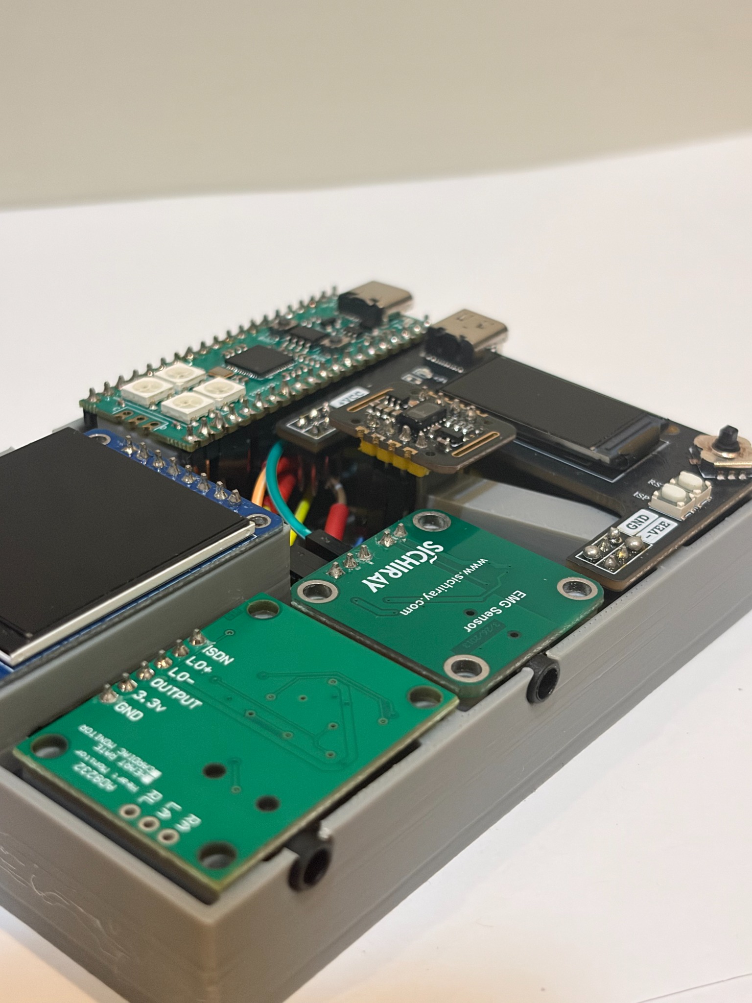
Inside the printed base
The physical prototype with the cover removed. Controller, display and sensor boards are fitted into the printed base.
Open original photograph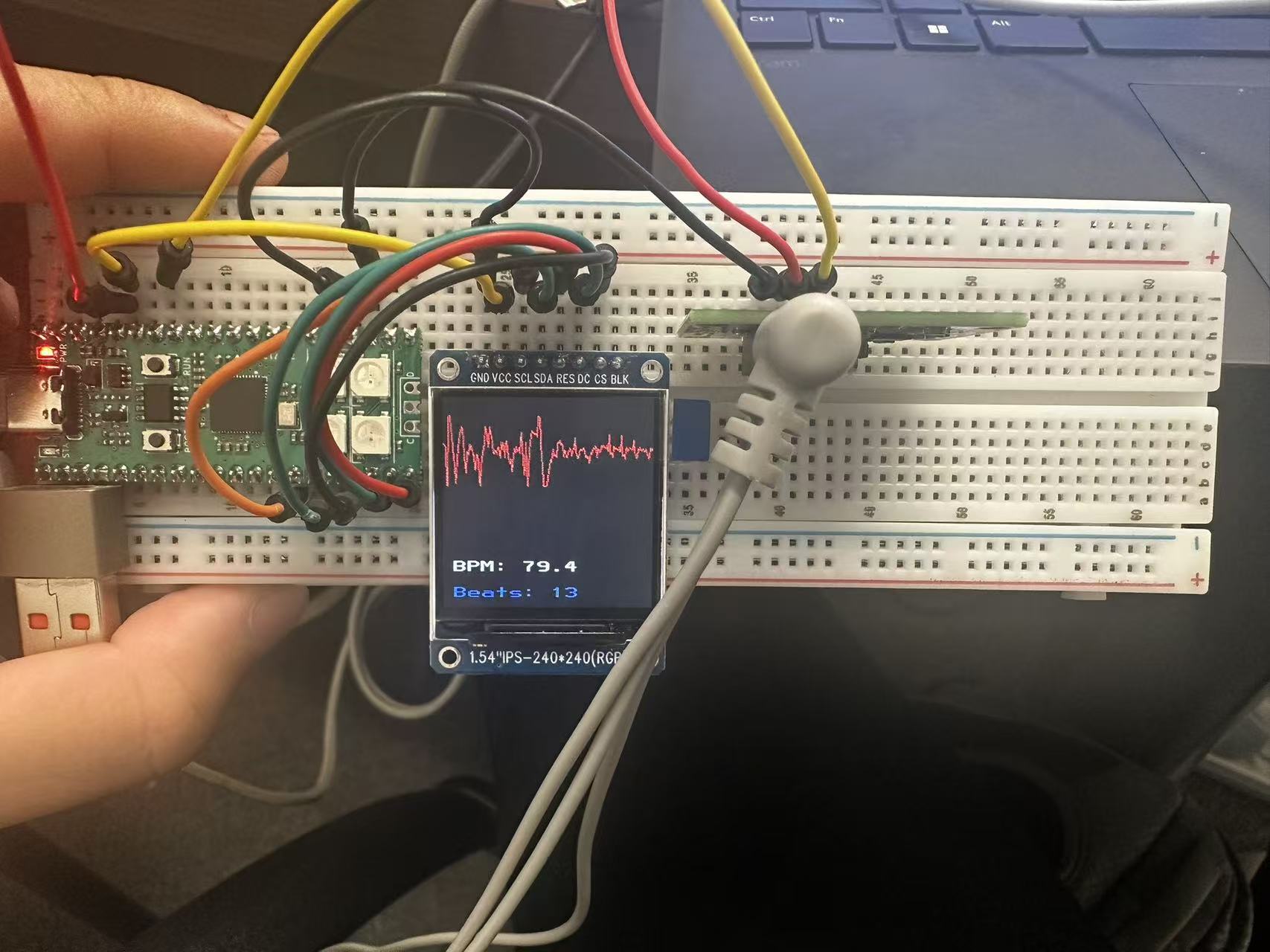
ECG display running
A development photograph records a red waveform, BPM and beat count on the display. It documents screen operation; the displayed estimate is not an instrument-comparison result.
Open original photograph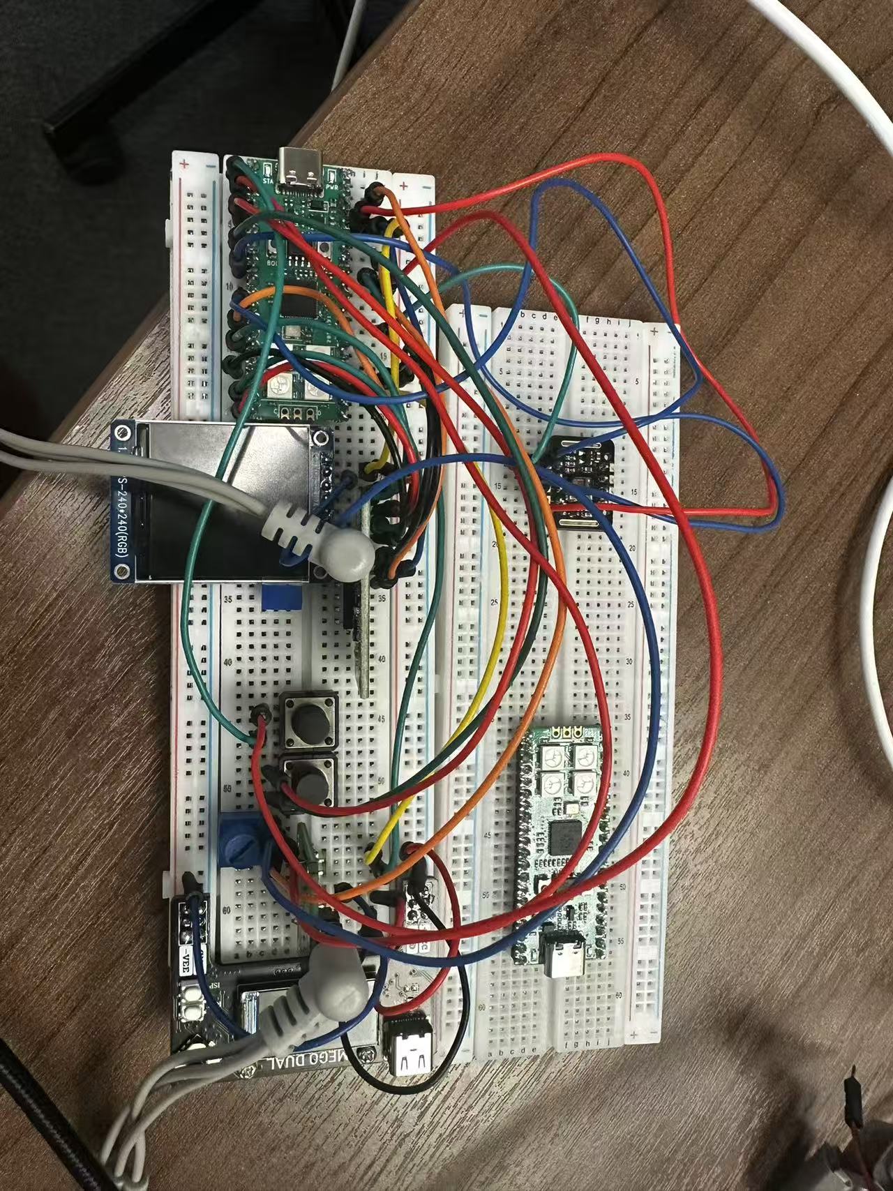
Breadboard integration
Overview of the assembled breadboard prototype before enclosure integration, including the controller, jumper wiring, display, buttons and sensing modules.
Open original photograph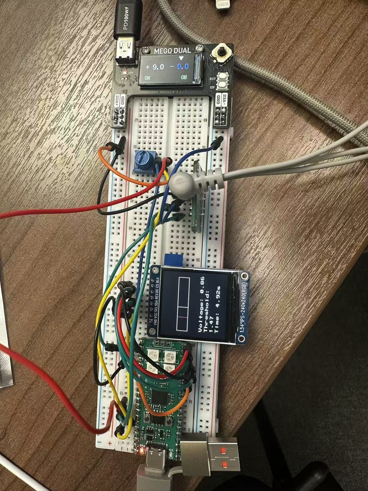
EMG development setup
An earlier threshold-control setup. The MEGO display shows +9.0 / -9.0 at this stage. This historical photograph is separate from the final build’s reported +5 V setting; it is not a wiring instruction or an independent rail measurement.
Open original photographThe photos document different development stages. They do not verify every connection, the displayed measurements’ accuracy or the final supply settings. The final build notes retain the builder’s reported power connections and the limits of the available evidence.