MAX30102 optical sensor
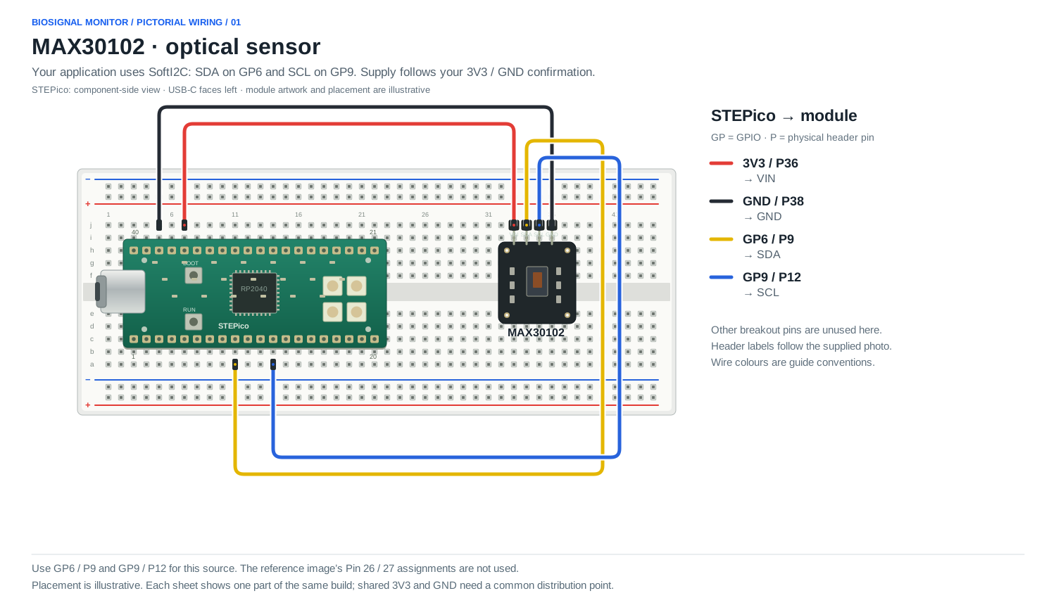
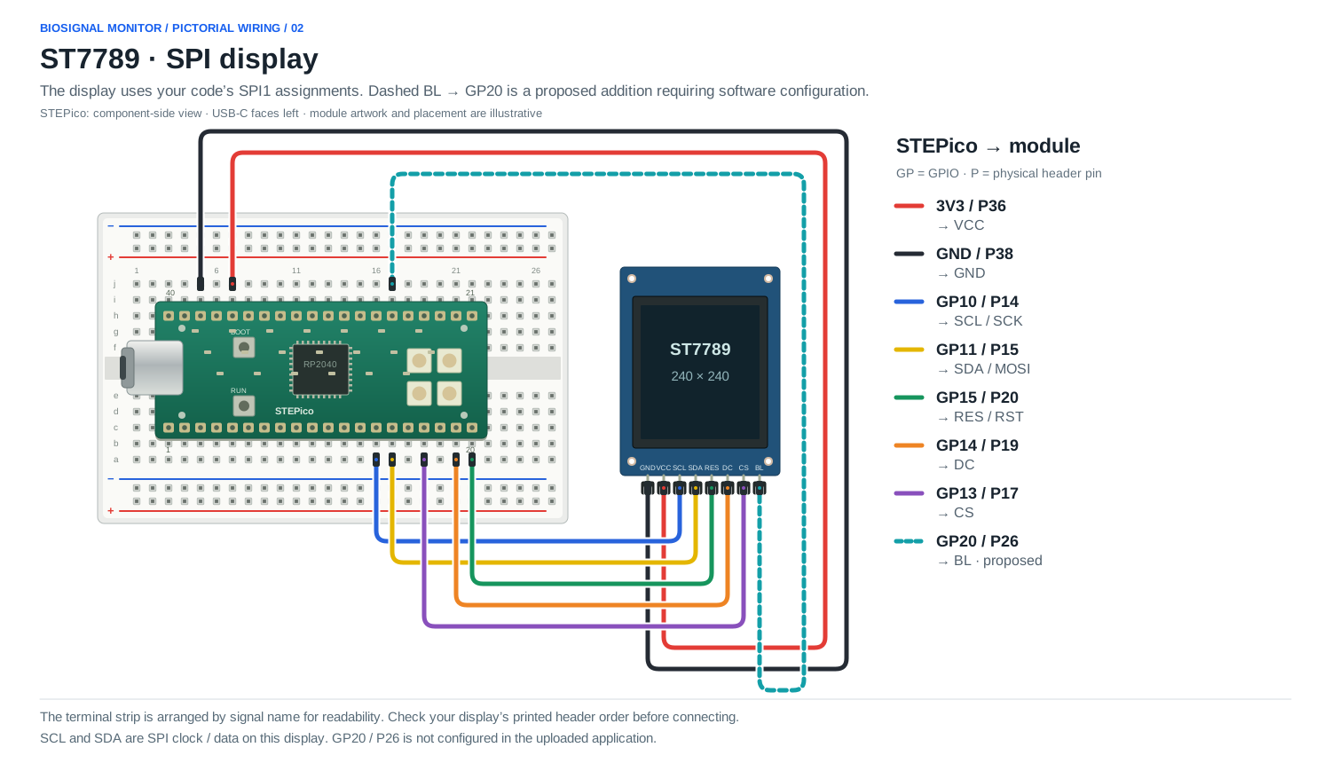
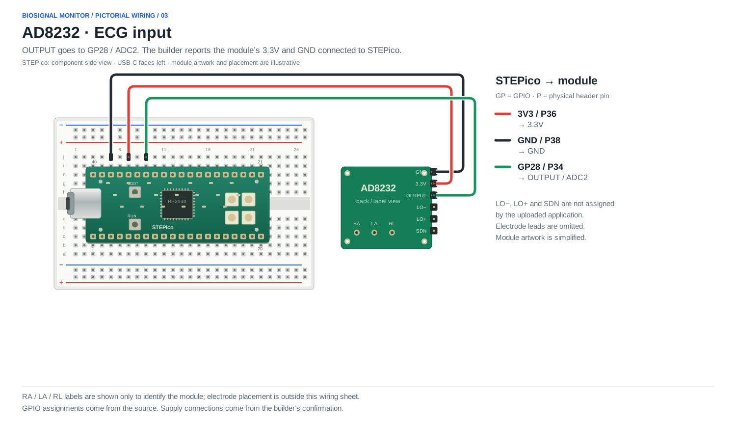
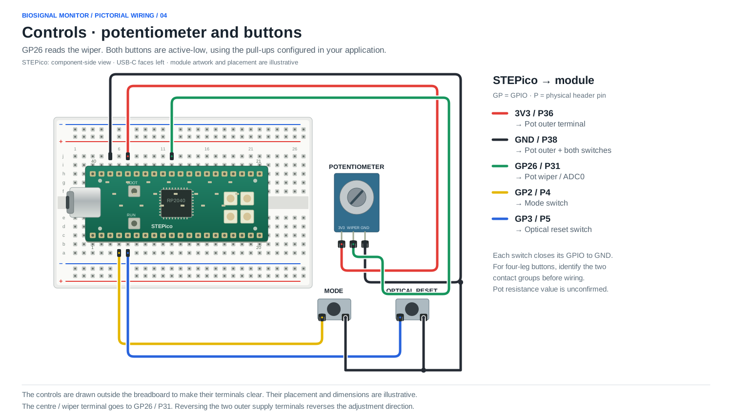
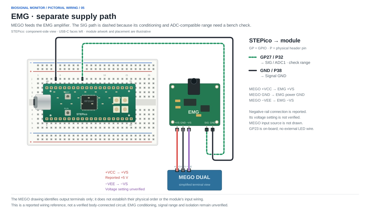
Five module sheets for the same STEPico build. GPIO assignments follow the uploaded application; non-EMG supplies follow the builder’s 3V3 / GND confirmation. Module artwork and placement are illustrative. The display header strip is arranged by signal name; match its printed labels before wiring.
GP = GPIO; P = physical header pin. STEPico is viewed from the component side, USB-C to the left. Use common distribution points for shared 3V3 and GND. White gaps separate crossing wires; only a marked dot indicates a shared junction.
Dashed BL → GP20 is proposed and needs software configuration. Dashed EMG SIG marks the pending conditioning / ADC-range check. MEGO’s negative voltage setting and input wiring remain unverified. These sheets do not establish a verified body-connected measurement setup.