PROJECT BUILD NOTES / DOCUMENTATION RELEASE · 21 OCT 2026
Portable 3-in-1 Biosignal Monitor
Source GPIO assignments, builder-reported power connections, module photographs and mechanical references.
Release status
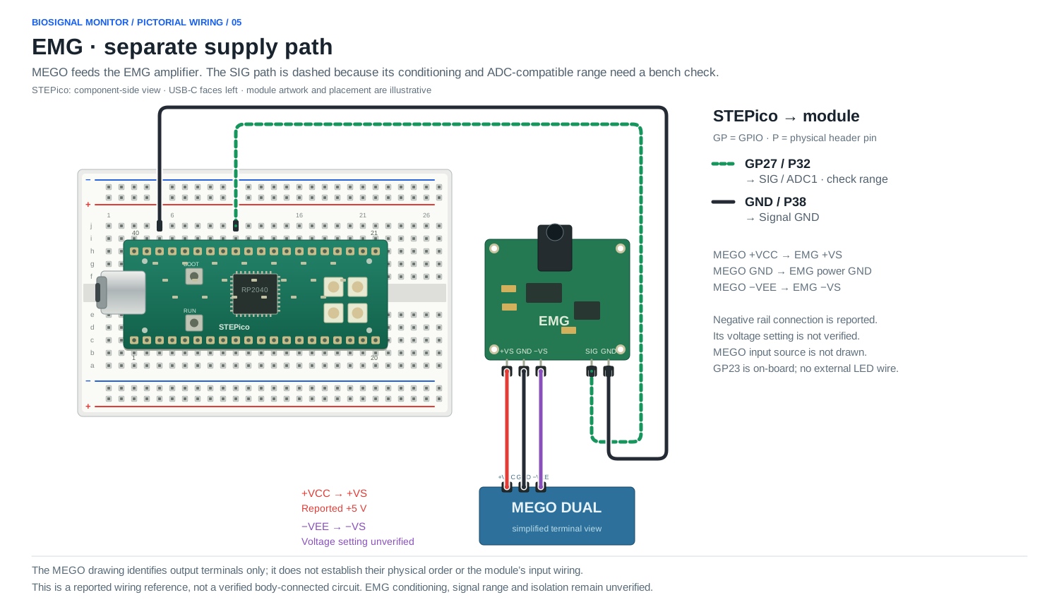
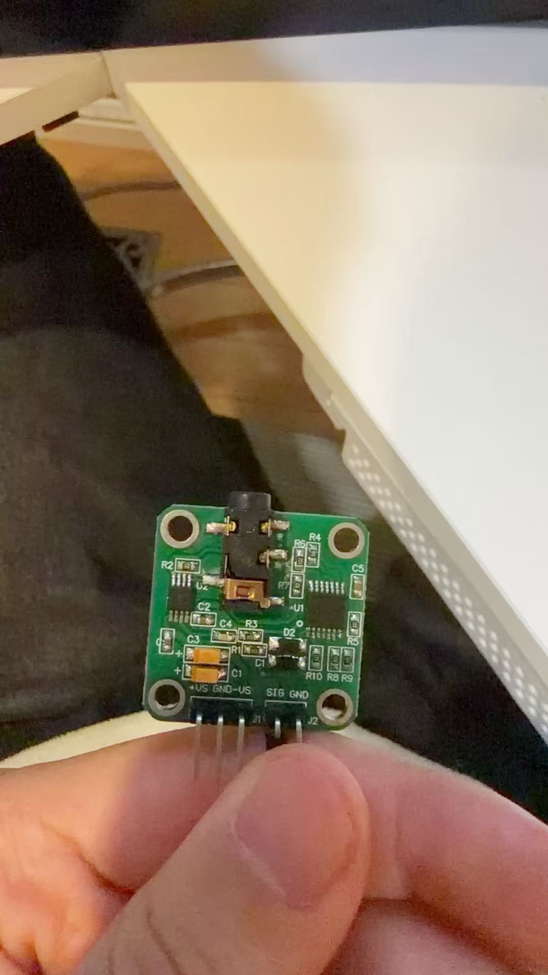
The application, both supplied fonts, both STL meshes and the supplied MEGO Fusion archive are preserved unchanged. The builder confirms STEPico 3V3 and GND for modules other than EMG. The EMG connection record uses MEGO +VCC → +VS, -VEE → -VS, power GND → MEGO GND and signal GND → STEPico GND. The positive output is reported as +5 V; the negative setting has not been verified.
The source ZIP now includes six unchanged Python files: main.py, the latest device copy of SpO2Calculators.py, both fonts and the two-file max30102 package. The Pico reports MicroPython 1.20.0 on RP2040. The supplied Shell output confirms a successful st7789 import, and the builder reports prior hardware tests passed.
Educational build reference. Supply wiring does not establish compatible ADC signal levels or a verified body-connected measurement system. Conditioning and isolation require a separately checked setup.
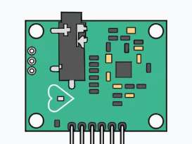
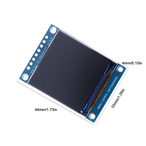
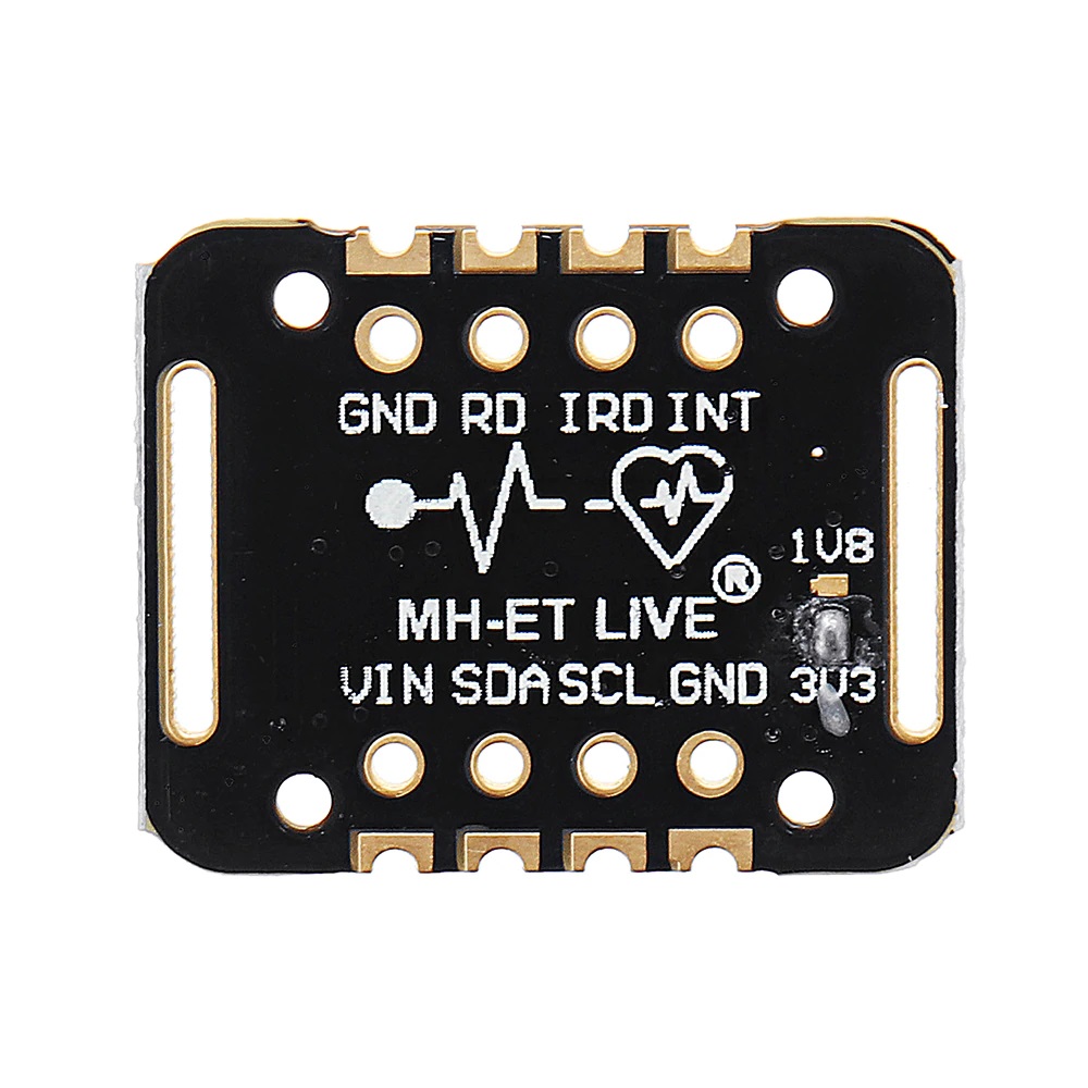
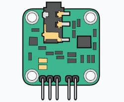
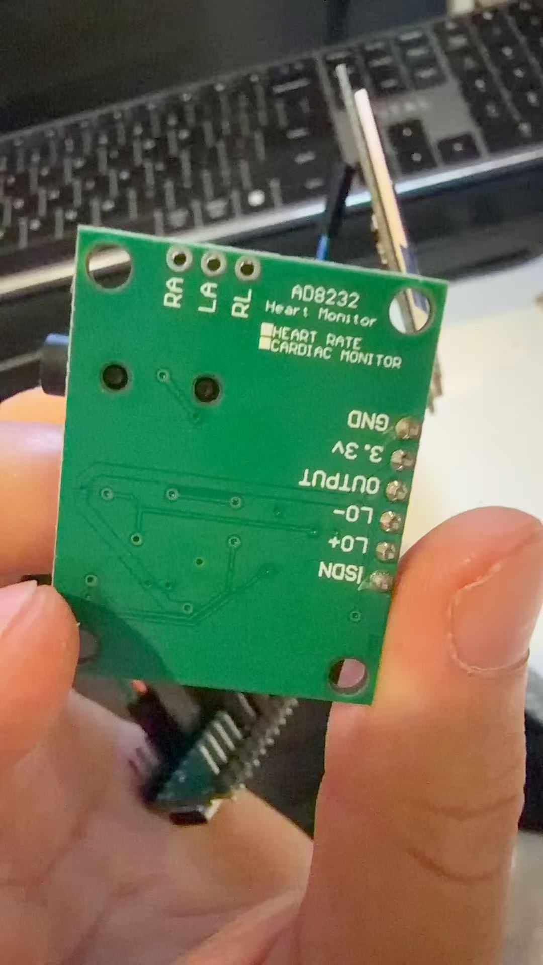
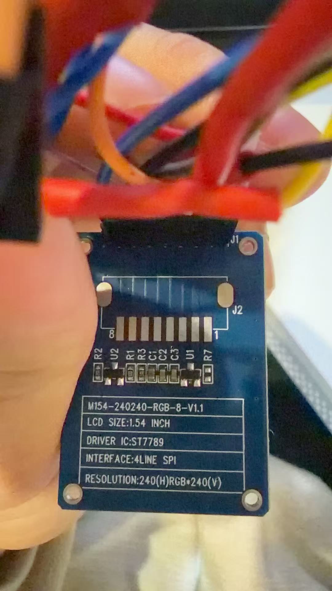
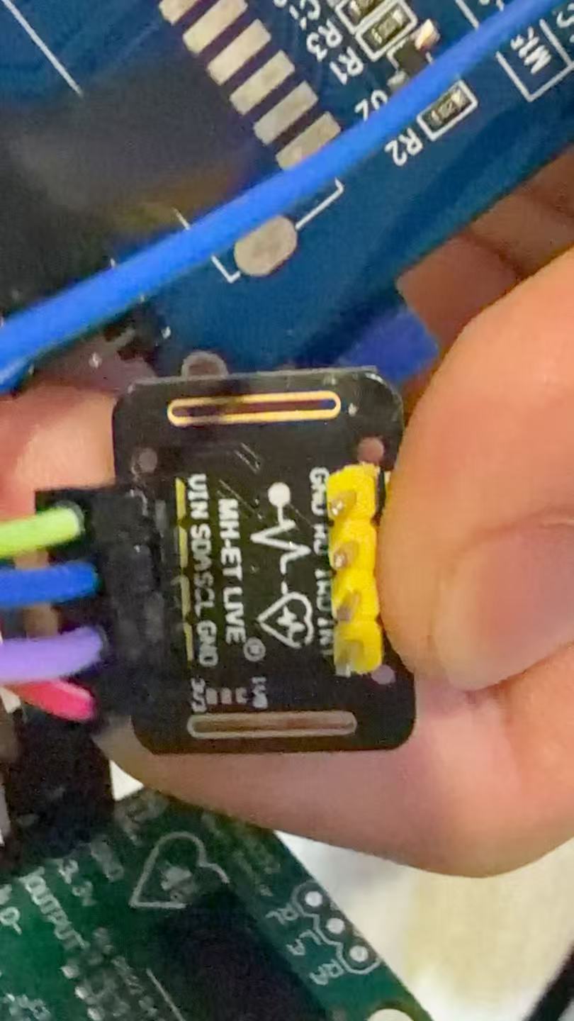
Product reference photos and details from the supplied CAD and EIM documentation screenshots. The original build photographs remain linked beside each reference image. The EMG illustration does not identify the amplifier IC in the actual build.
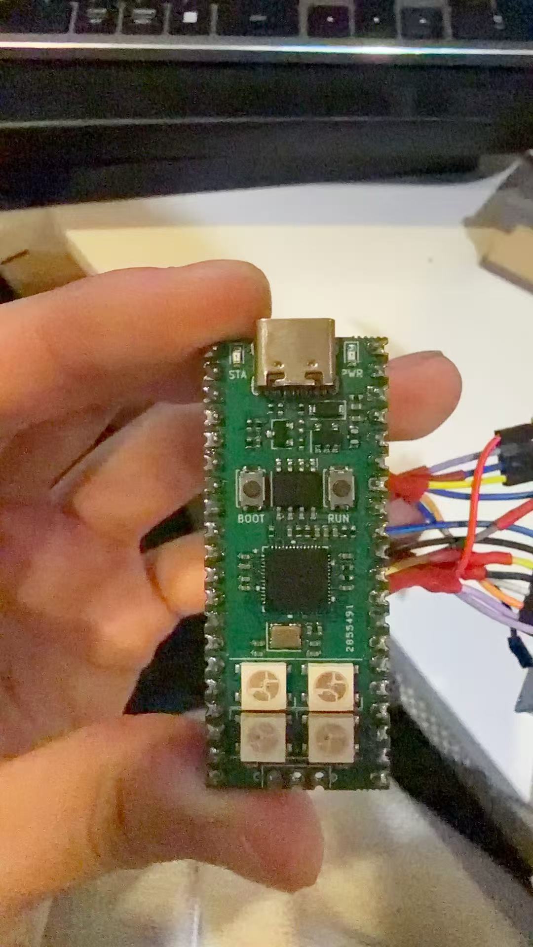
STEPico controller
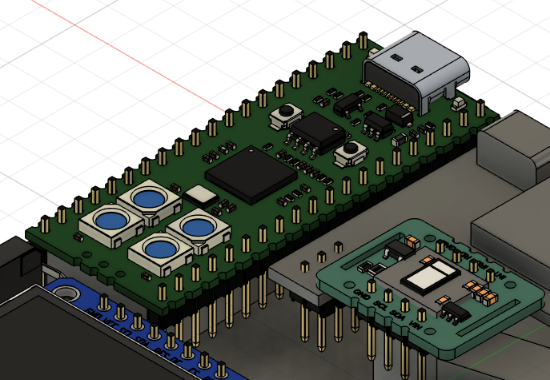
USB-C connector, BOOT / RUN buttons and four on-board LEDs. Detail from the supplied CAD layout.
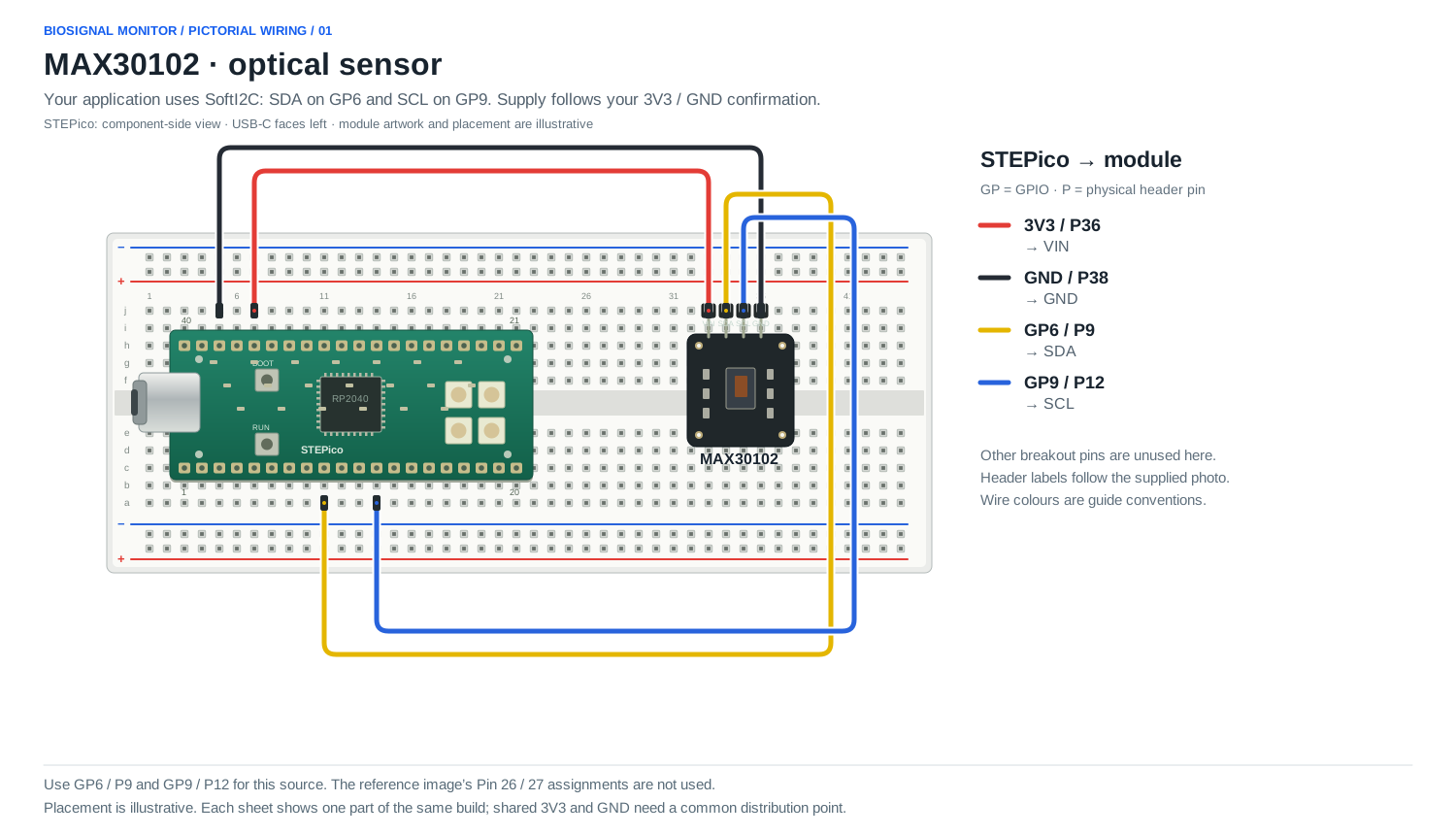
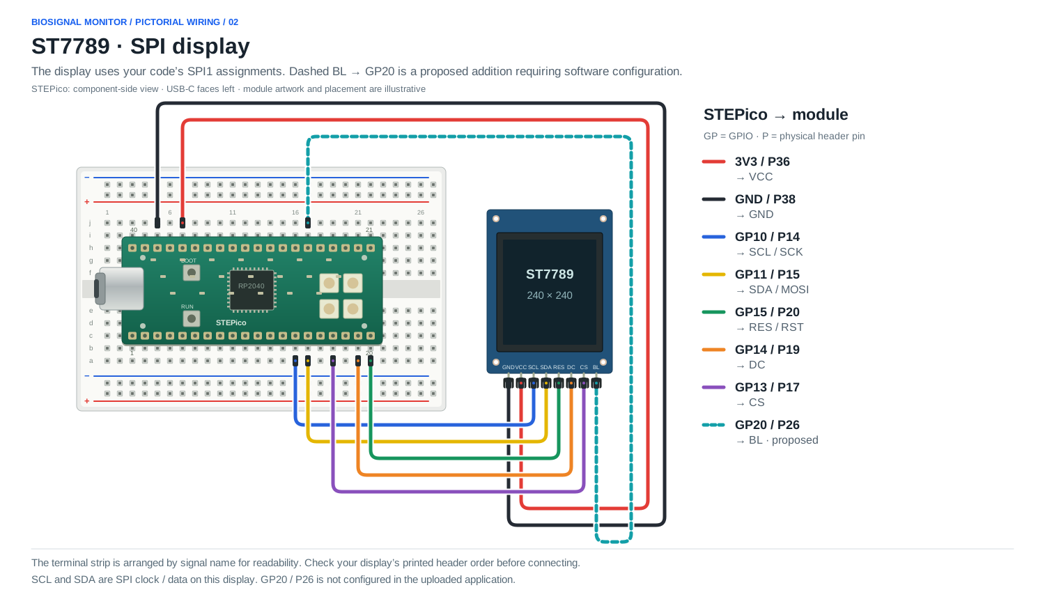
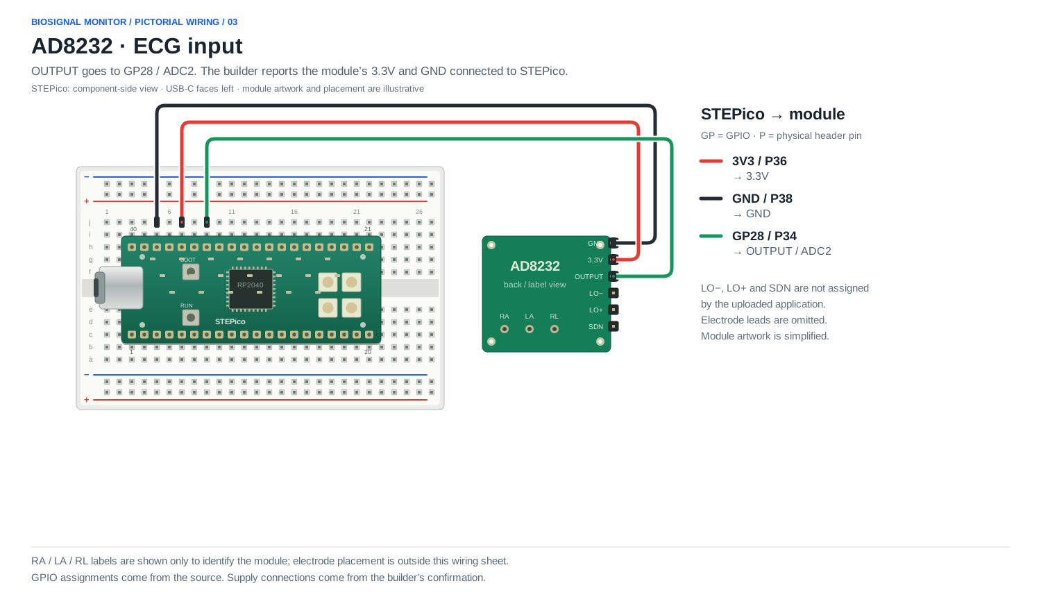
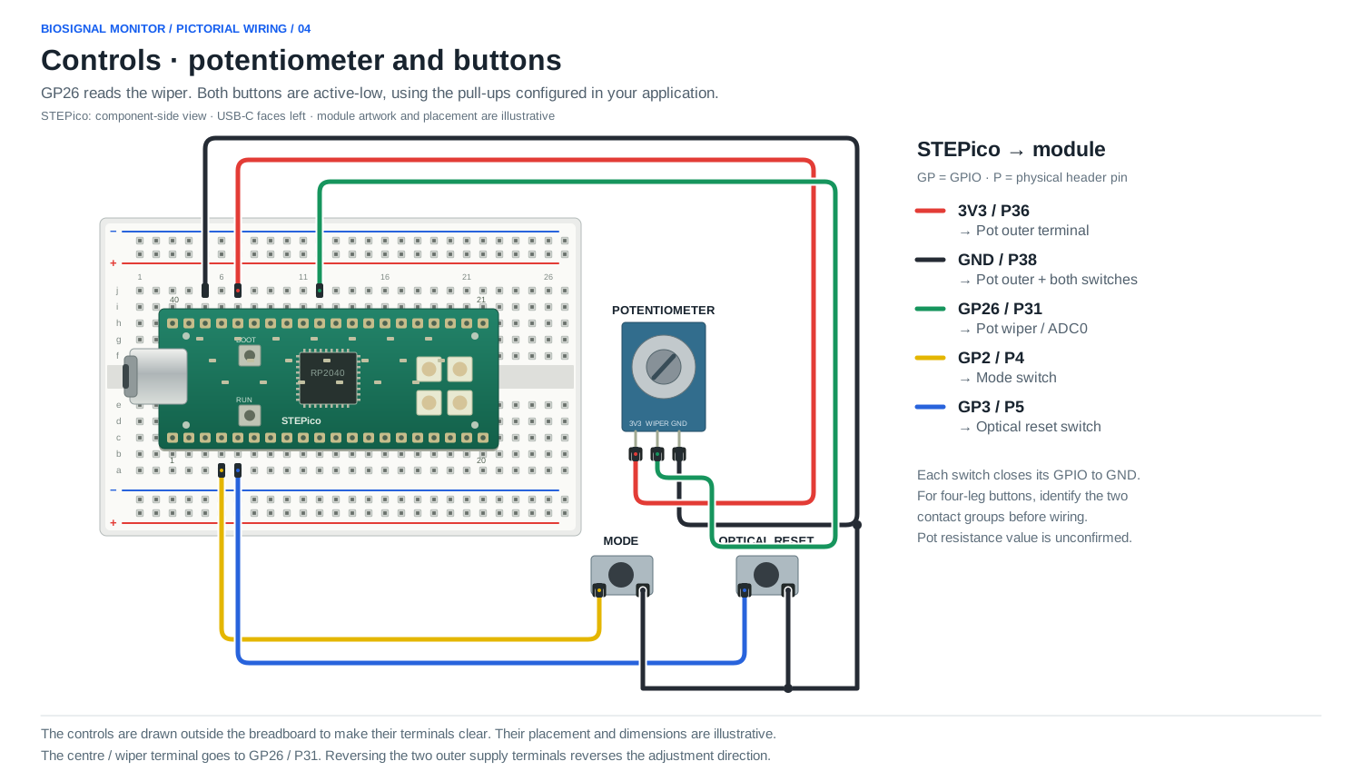
Five breadboard-style module sheets show GPIO labels and physical header-pin numbers. The same controller is repeated for clarity. Placement and module artwork are illustrative; the display header order must be checked against its printed labels. Shared 3V3 and GND need common distribution points.
Dashed display BL → GP20 is a proposed addition requiring software configuration. Dashed EMG SIG marks the pending conditioning / ADC-range check. The MEGO negative voltage setting and input wiring remain unverified.
Signal assignments from the source
GP labels are GPIO numbers, not physical header-pin numbers. The application uses SPI1 at a requested 40 MHz, polarity=1, phase=1. Its MAX30102 connection is SoftI2C on GP6 / GP9 at a requested 400 kHz.
Function
Module signal
Controller
Source line
ECG input
AD8232 OUTPUT (inferred module role)
GP28 / ADC2
38
EMG input
EMG module SIG
GP27 / ADC1
53
Threshold control
Potentiometer wiper
GP26 / ADC0
54
Display clock
ST7789 SCL / SCK
GP10
31
Display data
ST7789 SDA / MOSI
GP11
31
Display select
ST7789 CS
GP13
32
Display data / command
ST7789 DC
GP14
32
Display reset
ST7789 RES / RST
GP15
32
Optical data
MAX30102 SDA
GP6
72
Optical clock
MAX30102 SCL
GP9
72
Mode button
Active-low pushbutton
GP2
17
Optical reset button
Active-low pushbutton
GP3
70
On-board indicator
RGB LED data
GP23
63–64
Reported power connections
AD8232 3.3V, MAX30102 VIN and ST7789 VCC connect to STEPico 3V3; each GND connects to STEPico GND. Potentiometer outer terminals use 3V3 / GND and its wiper goes to GP26. These supply paths follow the builder’s confirmation.
GP20 is selected as an optional display-backlight pin for this guide. It is free in the supplied program and follows the manufacturer’s reference assignment. It requires matching software configuration and is not asserted as the existing physical connection.
The standard RP2040 ADC range is 0–3.3 V. EMG amplifier supply rails are separate from its signal output; check the output range and conditioning before connecting GP27.
Assembly outline
Open the two enclosure meshes and compare their board locations with the CAD layout. Verify model scale in the slicer; STL files do not declare units.
Record actual print material, orientation, settings, clearances and fasteners. These are not established by the supplied files.
Identify module connectors from the photographs. Plan access to USB-C, controls, the display and sensor connectors.
Trace the reported 3V3 / GND connections and the separate EMG supply path; check the analog conditioning and reference.
Use the source GPIO table for signal connections. GP2 selects the mode; GP3 resets the optical calculation buffers. Keep GP6 / GP9 for this SoftI2C source.
Record firmware and library versions, resolve the compatibility findings, then check display output, sensor detection, controls and all three modes on the device.
MEGO_Dual_v2.f3z is a module reference archive. Full assembly CAD, print settings and fastening details are still needed for a complete mechanical build guide.
STEPico setup · six steps
For a new board, follow all six steps. A board already running compatible MicroPython with st7789 can continue at step 5. These instructions adapt the manufacturer’s STEPico setup guide to the biosignal monitor’s display driver and source files.
Recorded working environment
The builder’s Shell reports MicroPython 1.20.0 on Raspberry Pi Pico / RP2040 and successfully imports st7789. The builder confirms earlier hardware tests passed. The exact original firmware image has not been identified.
1
Prepare Thonny and USB
Install Thonny from thonny.org. Connect STEPico with a USB-C data cable.
2
Choose the firmware
Use an RP2040 / Raspberry Pi Pico build that provides the st7789 display driver. The builder’s working board reports MicroPython 1.20.0; the exact original firmware image is unavailable. The driver project provides precompiled RP2 firmware as an upstream reference.
3
Enter BOOT mode
Hold BOOT, press and release RUN, then release BOOT. Alternatively, hold BOOT while plugging in USB. A drive named RPI-RP2 should appear.
4
Transfer the UF2 image
Drag the compatible .uf2 file onto RPI-RP2. STEPico restarts and the drive disappears. This installs the runtime; Python files are transferred through Thonny afterwards.
5
Connect the interpreter
In Thonny, select the MicroPython Raspberry Pi Pico / RP2040 interpreter and the board’s serial port. Open the Shell. For a new installation, import st7789 to confirm that the display driver is available.
6
Copy and start the project
Extract application-source.zip. In Thonny’s Files view, copy the four root Python files and the max30102 folder to the device root, preserving both files inside that folder. Open main.py and choose Run current script (F5).
A .uf2 file installs the board’s runtime. main.py and its libraries are copied into that runtime’s filesystem through Thonny. The st7789 project’s precompiled RP2 firmware is an upstream driver-inclusive reference; it has not been confirmed as the builder’s original image.
Directory structure
Path on Pico
Purpose
main.py
Project application
SpO2Calculators.py
Supplied calculator with reset()
vga1_16x16.py
16 × 16 display font
vga1_8x8.py
Font imported at startup
max30102/__init__.py
Optical sensor driver
max30102/circular_buffer.py
Driver buffer dependency
The two MAX30102 files belong inside the max30102 directory. The other four Python files belong in the device root. The supplied filenames containing upload suffixes have already been normalised in the source ZIP.
Supplied firmware references
UF2 block structure and internal version strings were inspected. These three uploaded files are references; they do not identify the current board’s reported 1.20.0 image. Their display-driver compatibility has not been established, and they are not bundled as project firmware.
Supplied filename
Internal version
RPI_PICO-20250415-v1.25.0.uf2
1.25.0
RPI_PICO-20250809-v1.26.0.uf2
1.26.0
RPI_PICO-20260824-v1.29.0.uf2
1.29.0
Software and installation
The builder supplied this Pico Shell result on 21 Oct 2026:
(name='micropython', version=(1, 20, 0), _machine='Raspberry Pi Pico with RP2040', _mpy=4358)
This identifies the reported runtime version and platform. The builder also supplied <module 'st7789'> as the result of importing the display driver. The exact original firmware image has not been supplied.
Files in application-source.zip
Path on Pico
Purpose / status
main.py
Current device application; byte-identical to the earlier supplied final program.
SpO2Calculators.py
Latest supplied calculator, renamed to match the import. Includes reset() and an incomplete-cycle guard.
max30102/__init__.py
Supplied optical sensor driver; original attribution and contents preserved.
max30102/circular_buffer.py
Supplied buffer dependency, unchanged from the earlier copy.
vga1_16x16.py
Original 16 × 16 font.
vga1_8x8.py
Original 8 × 8 font, imported at startup.
Copy and check
Extract application-source.zip on the computer and preserve the max30102 directory.
Connect the Pico to Thonny and select its MicroPython interpreter. Open View → Files and preserve the existing device files before copying the release.
Copy the four root Python files and the max30102 directory into the Pico root. The directory contains __init__.py and circular_buffer.py.
On a fresh Pico, provide a compatible runtime with the st7789 driver available. The builder’s current Pico already imports it successfully; the source ZIP contains no firmware image.
The builder confirms prior successful tests of the display, controls and all three modes. This operational status is recorded from that confirmation.
Firmware image and operating record
A .uf2 file is a board firmware image used to install the runtime onto the Pico. It is separate from main.py and the Python library files. A display driver can be compiled into a firmware build. Supplied 1.25.0, 1.26.0 and 1.29.0 files are recorded as references above. A fresh-board installation needs a compatible st7789 driver runtime; those files do not establish the exact original 1.20.0 image.
The builder confirmed prior hardware tests passed on 21 Oct 2026; the original test date and detailed logs were not supplied.
Code review findings
Host checks pass for Python syntax, the calculator constructor and reset, empty / flat input and complete synthetic wave cycles. Every MAX30102 method called by main.py exists in the supplied driver. These checks do not run the code on the physical Pico.
A zero-baseline stress input still triggers ZeroDivisionError in the calculator. main.py also divides red_ratio by ir_ratio without excluding zero. The supplied buffer’s pop_head() has an issue outside the application’s current pop_red_from_storage() / pop_ir_from_storage() path. All files are preserved unchanged; these findings are documented for a later code revision.
The earlier candidate calculator lacked reset(); the latest device copy supersedes that candidate and includes the method. Its incomplete-cycle guard also supersedes the earlier missing-guard finding. The original firmware image and exact display driver version remain undocumented. The display import succeeds and prior hardware operation is confirmed by the builder.
Implemented modes and test record
ECG: GP28 waveform, threshold-crossing pulse estimate from the preceding ten seconds, with a two-second refresh after the first window.
EMG: GP27 reading compared with the GP26 potentiometer threshold. The displayed “voltage” divides read_u16() by 30000, so this prototype scale needs review.
Optical: MAX30102 red / infrared readings and a prototype oxygen-saturation estimate. The GP3 reset is not calibration against a reference instrument.
The supplied August 2025 conversation reports that replacing the STEPico restored operation and stopped observed heating. It does not establish the cause of the earlier fault. No servo or PWM output is implemented in the uploaded final program. Its sensor-missing startup message does not establish complete recovery behaviour. The builder reports prior successful hardware tests of the supplied program.